Hivoduct Pressurized Air Cable Technology
Building or upgrading high-voltage lines becomes increasingly difficult due to environmental concerns and impact on neighbourhood. Using underground high-voltage cables can mitigate some related problems - but adds new ones like thermal limitations, joints, magnetic field emissions and specific earthing and reactive power compensation requirements.
Hivoduct pressurized air cables are a new technology with better technical parameters than OHL and XLPE cables. They use pressurized air for insulation and a coaxial tube-in-tube conductor design - similar to GIS busducts.
GIS busducts and GIL (=Gas insulated lines) today mostly use SF6 as insulation gas. There is a strong global trend in research and product development to replace SF6 in these applications. Hivoduct pressurized air cables replace GIS exit busducts and GIL with the same performance but without using SF6.
Replacing SF6 gas requires a new product design - as it is fundamental to the performance of high-voltage products.
Hivoduct has done a new design from the bottom-up and developed a new technology "pressurized air cables" which cover the MV and HV range. This was accomplished by incorporating the learnings from over 50 years of gas-insulated high-voltage products and adding a number of new and unique features.
Our main guideline for development was our mission:
Reduce the visual impact | Pressurized air cables are mostly layed underground - like XLPE cables. -> Visible only at the ends when it connects to existing lines or substations. |
No GWP of the insulation material | Pressurzied air cables use air for insulation (80% NO2, 20% O2, dry). -> Air has no GWP (Global Warming Potential). (SF6 has a GWP of 23000 XLPE has GWP due energy intensive production) |
Reduce electromagnetic field emissions | Pressurized air cables use a coaxial aluminum tube arrangement (like GIL) with rigid, conductive and grounded enclosures. -> No outside electric fields. Minimum outside magnetic fields. |
Reduce material | Pressurized ai cables have an aluminum conductor & enclosure with sufficient cross-section and optimum diameter ratio. Use distant spacers to keep them coaxial. Optimize all together with air pressure. Optimize 3-phase arrangement. Optimize on-site laying options and minimize digging. Enable co-location with existing infrastructure. -> No copper. No XLPE. No concrete pouring. No need for double systems. Less digging and filling. |
Reduce losses | Large conductor cross-section leads to less resistance and therefore less losses. Smaller epsilon_r and bigger air gap leads to less AC losses (capacitive currents). Smooth and round dielectric design avoids corona losses. Double sealing system avoids pressure losses. |
The result from this development process is the Hivoduct pressurized air cable design. Below are some key points for the development.
Insulation design
Using the well-known and researched dielectric performance of air , we designed optimal conductors, enclosures, spacers and shields to work with air pressures up to 10 bar.
The calculation shows an example for a rated voltage of 145 kV - which according to IEC 62271 standard requires an impulse withstand voltage (BIL) of 650 kV. To include some margin, a typical design may be done for ~700 kV.
Air is used with increased pressure and larger insulation gap.
The electric field stress is highest on the surface of the conductor. We've chosen a closest to optimal diameter ratio of OD/ID = 2.7 = e.
Single-phase enclosures ensure the most ideal coaxial arrangement and best use of the air insulation space.

Mechanical design
The key items for mechanical design are:
- Cope with air pressure up to 10 bar to cover a wide range of rated voltage levels.
Note that multiples of this pressure are specified for bursting pressure type tests (e.g by SVTI 704, EN 12952, EN 12953, EN 13445, ASME, etc.) - Use less sealing surfaces and a double sealing system for air tightness over the lifetime of the product.
- No welded flanges: As gas-tight welding of thin-walled aluminum tubes is a tricky process (in the factory and specifically on-site) and non-destructive disassembly is not possible, we avoided welded flange connections.
- No bolted flanges: Typically, a bolted flange requires 16 bolts + 32 washers + 32 nuts. This sums to a tremendous amount of small parts and manpower requirement for assembling an extended installation.
-> Example for 1000 m with bolted flanges:
3 phases * 1 Flange/5m * 1000m * (16+32+32) = 48'000 items.
In addition, checking the proper tightening of each bolt is a process prone to failure.
Therefore, we avoided bolting of pressurized air cable flanges. - Use flexible elements so the pressurized air cables can be laid e.g. along a road or tunnel and follow the bending and up's and down's of the road.
This includes flexible angle pieces and compensators to handle thermal expansions during operation. - Seal the flanges against water or dust ingress if required.
- Enable quick assembly and disassembly for re-arranging, extensions, maintenance and repair.
A feature specifically useful for test- or lab installations where frequent non-destructive disassembly and rearranging is required.
Hivoduct cable components portfolio:
- Straight busduct: Any length <= 5m
- Fixed angle piece: 30°, 60°, 90°
- Variable angle piece: Flexible angle +- 10° in all directions
- Length compensator: dL = 0-80 mm
- Lateral dismantling piece: To remove a section of a Hivoduct line for maintenance while the rest can stay in place.
- Bushing interface: To connect to High-Voltage lines
- GIS Interface: To directly connect to single-phase enclosed Gas-Insulated Switchgear (SF6 or SF6 free)
- Cable interface: To provide the same interface as specified in IEC62271-209 for HV Cables.
- A roller system: To install, align and maintain pressurized air cables on-site in compact pipes or tunnels and in confined space
- Air filling and pressure monitoring system
- Assembly and disassembly tools
The set of cable components can be freely combined with each other to provide the required product characteristics.
Proper selection and combination is part of the engineering process.
An on-line configurator helps to choose the right options and technical parameters and instantly provides a budgetary price.
Installation design
For underground or enclosed applications, it is key to require the least space and least effort for conduits, laying, digging and trenching. The main design features to enable this are:
- Low losses: To avoid spacing between phases for thermal reasons and to avoid the need for parallel systems.
Low losses are engineered by providing sufficient conductor cross section. - Compact dimensions: To use less space and require smaller trenches or conduits. Compact outer dimensions are achieved by avoiding flanges and bolts.
- Roller system for installlation into pipes and confined spaces. The roller system remains in the piper during operation and can be used for repair & replacement.
- Long sections of aircables can be inserted into confined spaces such as pipes, troughs, conduits or below tunnel pavements without the need for access for workers or machinery.
- Minimum bending radius. The 90° angle pieces enable zero bending radius and therefore going around corners or follow roads or other parallel infrastructure.
Note: Engineering effort increases for "curvy" installations . - Passive internal arc protection. The rare event of an internal arc fault is not noticeable on the outside. This enables pressurized air cables to share infrastructure space with roads, railways, communication infrastructure, conduits, tunnels, bridges and others.
- Fire protection and no harmful gas. Pressuirized air cables have thick & robust aluminium enclosures. Aluminium does not burn. Double sealing avoids air leakage. But even if the pressurized air leaks, it is still air.
This enables co-location with critical infrastructure. - The (optional) supply duct may be used for low-voltage cables, fiber-optic cables, air supply or others in parallel to Hivoduct.
See more details in the "products" tab.
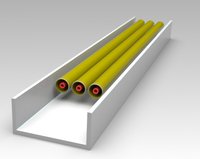
Application examples:
Hivoduct pressuriuzed air cables in pre-casted concrete trench or in a tunnel below pavement or in a pipe underground.
Trenching can be avoided using Micro-tunneling technology with concrete pipes. The roller system allows quick installation and removal.
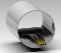
Example: Pressurized air cables in a tunnel:
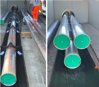
Example: Installation of roller system in a trench
Lowest outside electromagnetic fields
Single-phase coaxial conductor arrangements with conductive and grounded enclosures have the general advantage of featuring the least outside electromagnetic fields:
The electric field is completely shielded by the closed, conductive, grounded aluminum enclosure.
The magnetic field emissions depend on the actual current flow through the conductor. Enclosures are conductive and solidly grounded. Actual current in the conductor induces similar enclosure currents which will cancel out most of the outside magnetic field. This is why the outside magnetic field of pressurized air cables always remains significantly lower than that of HV lines or cables.
See an example simulation here: G10 triangular arrangement with 3*3150 A at 50 Hz, layed 1 m underground. Green area is 1 to 3 microTesla. Red area is 10 microTesla.
The remaining outside magnetic fields from pressurized air cables fade away within a few meters. Therefore, if laid e.g. 1 m below ground or deeper, a very low limit value of 1 uT may be achieved during average current flow on ground level directly above.
Hivoduct pressurized air cables are the best technical option if low outside electromagnetic fields are required for any given current or power transmission capacity.
Literature
[1] Innovation to reduce the environmental impact of HV transmission lines: High-efficiency pressurized air cable technology. W. Holaus, IEEE Workshop 12/2021
[2] Pressurized air insulated cables: A novel, compact GIL design for 12 kV- 420 kV: Design, Simulation, and Test results. W. Holaus et. al. CIGRE 08/2022
[3] Test- und Betriebserfahrung mit einer 145-kV-Druckluftkabel-Pilotanlage. W. Holaus, GIS Anwenderforum Darmstadt 09/2022
[4] Pressurized Air Cables - a new technology for sustainable energy transmission 12 kV - 420 kV. W. Holaus, VDE Berlin 11/2022
Background information:
Gas Insulated Transmission Lines
Gas Insulated Lines (GILs) are coaxial arrangements of a tube-shaped conductor centered inside a tube-shaped gas-tight enclosure. An insulation gas at elevated pressure is used to isolate the conductor from the enclosure. They have a long history in high-voltage transmission and its characteristics are well known.
Hivoduct aircables are different - by using air for insulation, introducing flexibility like other cables, having a different design, different manufacturing and installation methods. However, the physical working principle is the same - therefore some background information below for readers new to this topic.
Further read on GIL technology:
For detailled information: Hermann Koch: Gas Insulated Transmission Lines ISBN 978-0470665336
A good summary on GIL technology and characteristics is provide here by Mike Rycroft:
Several manufacturers offer GIL products
http://rbc-energo.ru/en/tokoprovod/s-elegazovoj-izolyaciej/rbc-gil/
https://www.azz.com/products/bus-systems/sf6-gas-insulated-lines
Used insulation gases
Existing GIL products use SF6 or SF6 gas mixtures or other specific synthetic insulation gas mixtures to provide the main insulation between the high-voltage conductor and the enclosure. Research for a variety of gas alternatives is ongoing.
https://www.mdpi.com/1996-1073/13/7/1807/pdf
https://new.abb.com/high-voltage/gis/reference-ewz-oerlikon-substation-switzerland
Welding and bolting
Traditional GIL designs use on-site welding of enclosure tubes or bolted flanges to connect single tubes into extended GIL sections.
Examples: http://www.wartmann-technology.com/en-us/Power-engineering/Gas-insulated-transmission-lines
https://docplayer.org/48647819-Uebertragungstechnologie-fuer-hohe-leistungen-siemens-com-energy.html
DC GIL:
Since the advent of high-voltage DC transmission, evaulation of GIL technology for this application case is ongoing:
Studies on electromagnetic fields
There are numerous studies on electromagnetic fields of different transmission technologies. It is a common understanding that GIL technology offers the least outside field emissions, as they use a conductive and solidly grounded enclosure. Example: http://www.emfs.info/sources/underground/gil/