 deDeutsch

Willkommen bei Hivoduct
Dem Unternehmen für nachhaltige Stromübertragung, massgeschneiderte Produkte & bahnbrechende Technologie
Druckluftkabel sind die nachhaltige Lösung für effiziente und zukunftsorientierte Stromübertragung. Wir bieten innovative, umweltfreundliche Technologien für eine bessere Energiezukunft. Profitieren Sie von massgeschneiderten Lösungen, die Effizienz, Sicherheit und Nachhaltigkeit vereinen.

Unsere Vision
Druckluftkabel sind der neue Standard für die elektrische Energieübertragung
News
Bleiben Sie auf dem Laufenden! Hier finden Sie die neuesten Entwicklungen und innovativen Projekte rund um unsere Unternehmung
 18. März 2026
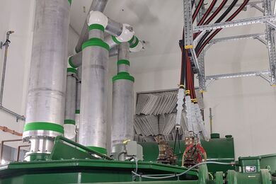
Erfolgreicher Vor-Ort-Test der ersten Druckluftkabel-Verbindung in der Schweiz


Events
Werfen Sie einen Blick auf unsere bevorstehenden Veranstaltungen und sichern Sie sich Ihren Platz. Lassen Sie sich inspirieren und tauchen Sie ein in eine Welt voller Innovation und Erlebnisse. Wir freuen uns darauf, Sie persönlich begrüssen zu dürfen!
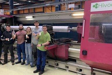
Möchten Sie vor Ort erleben, wie unsere hochwertigen Rohre produziert werden? Unsere Firmenbesichtigung bietet faszinierende Einblicke in die Prozesse, die hinter unseren erstklassigen Produkten stehen. Nutzen Sie die Gelegenheit, hinter die Kulissen zu schauen und unser Engagement für Qualität und Innovation hautnah mitzuerleben.
 07. April 2026 bis 09. April 2026, Dubai World Trade Centre, Dubai
Middle East Energy 2026 – Dubai

 16. Juni 2026 bis 17. Juni 2026, Universität Stuttgart, Institut für Energieübertragung und Hochspannungstechnik
Stuttgarter Hochspannungssymposium 2026


 17. November 2026 bis 19. November 2026, Power Transmission & Distribution Messe in Köln
Power Transmission & Distribution Messe
Hivoduct in den Medien
Innovationen von Hivoduct stossen auf grosses Interesse in der Fachwelt und den Medien. Hier finden Sie eine Auswahl aktueller Artikel, Blogbeiträge und Erwähnungen über unser Unternehmen und unsere Technologie .
- Electrosuisse-Video - Oktober 2025
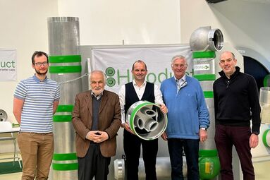
Ende August fand bei Hivoduct ein Event zur Vorstellung unserer Technologie statt. Electrosuisse hat diesen Anlass begleitet und ein kurzes Video veröffentlicht, das einen Einblick in die Funktionsweise und die Besonderheiten von Druckluftkabeln gibt. LINK - Swissgrid Blog – Oktober 2025
Swissgrid berichtet über das gemeinsame Pilotprojekt in Spreitenbach. Dabei wird erstmals ein Druckluftkabel im Übertragungsnetz getestet, um die Vorteile – insbesondere die deutlich geringere Blindleistung – im praktischen Einsatz zu demonstrieren. LINK - Cableizer-Blogbeitrag – Januar 2025
Der Blog von Cableizer behandelt die Pilotinstallation von Druckluftkabeln (Compressed Air Cables) durch Hivoduct in einem Versorgungs- und Servicetunnel unter einem Autobahntunnel. Der Beitrag beleuchtet insbesondere die technische Durchführung, die begleitenden Prüfungen und die Bedeutung für die Hochspannungs-Technologie. LINK - Baublatt-Artikel – Oktober 2024
Das Baublatt berichtet über neuartige Erdkabel und deren Potenzial, Transportverluste in Stromnetzen deutlich zu reduzieren. Im Beitrag wird die Technologie von Hivoduct als Beispiel für innovative Lösungen in der Energieübertragung vorgestellt. LINK
Hivoduct Druckluftkabel -Zukunftsweisende Technologie für eine nachhaltige Energieübertragung
Unsere innovative Druckluftkabel-Technologie setzt neue Massstäbe in der Energieinfrastruktur. Sie vereint höchste Effizienz, maximale Sicherheit und Umweltfreundlichkeit – perfekt für moderne, zukunftssichere Netzlösungen.
- Umweltfreundlich – Kein SF6, PFAS-frei, null Emissionen
- Maximale Effizienz – Geringe Verluste bei hohen Strömen, optimiert für höchste Leistungsfähigkeit
- Höchste Sicherheit – Geerdete, berührbare Gehäuse für zuverlässigen Schutz
- Platzsparendes Design – Kompakte Verlegung ohne Muffen, reduzierte Baukosten
- Perfekt für Tunnel & unterirdische Anwendungen – Keine Brandlast, ideal für enge Räume
- Flexibel & wartungsfreundlich – Schraubenlose, demontierbare Flansche für eine einfache Wartung
Hivoduct – Die beste Wahl für zukunftssichere Energieübertragung!
Gestalten Sie
Ihre perfekte Leitung!
Nutzen Sie unseren benutzerfreundlichen Online-Konfigurator und erstellen Sie Ihre massgeschneiderte Leitung – schnell, einfach und individuell.
